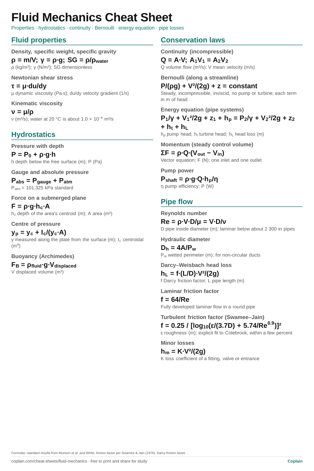
The equations of an introductory fluid mechanics course on one page: properties and viscosity, hydrostatic pressure and forces on surfaces, buoyancy, continuity, Bernoulli and the energy equation, momentum, Reynolds number and pipe friction losses. Each line lists its variables and SI units.
Pipe flow: formula, then every variable with its unit
Quantity
Formula
Variables and units
Reynolds number
Re = ρ·V·D/μ = V·D/ν
D pipe inside diameter (m); laminar below about 2 300 in pipes
Hydraulic diameter
Dh = 4A/Pw
Pw wetted perimeter (m); for non-circular ducts
Darcy–Weisbach head loss
hL = f·(L/D)·V²/(2g)
f Darcy friction factor; L pipe length (m)
Laminar friction factor
f = 64/Re
Fully developed laminar flow in a round pipe
Turbulent friction factor (Swamee–Jain)
f = 0.25 / [log10(ε/(3.7D) + 5.74/Re0.9)]²
ε roughness (m); explicit fit to Colebrook, within a few percent
Minor losses
hm = K·V²/(2g)
K loss coefficient of a fitting, valve or entrance
How to use this cheat sheet
Choose two points where you know the most (a free surface, a jet open to the atmosphere, a gauge) and write the energy equation between them. Atmospheric pressure cancels when both points are open to it.
Work in heads (metres or feet of fluid) for pipe systems; pressure terms become P/γ and every term then has the same unit.
Check the Reynolds number before you pick a friction factor. Laminar and turbulent flow use different formulas, and the Moody chart’s laminar line is f = 64/Re.
Example: Head loss and pressure drop in a water line
Given
Water flows at Q = 3.0 L/s through L = 40 m of straight, horizontal steel pipe, inside diameter D = 50 mm
Roughness ε = 0.045 mm (typical for commercial steel)
Water: ν = 1.0 × 10⁻⁶ m²/s and ρ = 998 kg/m³ (typical values near 20 °C); g = 9.81 m/s²
Find
The Reynolds number
The friction factor (Swamee–Jain)
The head loss and pressure drop
Solution
Mean velocity from continuity.A = π(0.050)²/4 = 1.963 × 10^-3 m²; V = 0.0030/1.963 × 10^-3 = 1.528 m/s
Reynolds number: well above 2 300, so the flow is turbulent.Re = V·D/ν = 1.528 × 0.050 / 1.0 × 10^-6 = 76 400
Darcy–Weisbach head loss.h_L = 0.0226 × (40/0.050) × 1.528²/(2 × 9.81) = 2.15 m
Horizontal pipe, constant diameter: the pressure drop is ρ·g·h_L.Δp = 998 × 9.81 × 2.154 = 21 100 Pa
Answer: Re ≈ 76 400 (turbulent); f ≈ 0.0226; h_L ≈ 2.15 m; Δp ≈ 21.1 kPa.
Printable cheat sheet
The PDF is one US Letter page that also prints on A4 without cropping. The 2:3 PNG is the same sheet as an image, sized for a phone lock screen or a pin. Both are made from the formulas in the tables above, so they always match.
Along a streamline in steady, incompressible flow with negligible friction and no pump or turbine between the two points. Once a pipe is long or has fittings, use the energy equation with head loss instead.
Darcy or Fanning friction factor?
This sheet uses the Darcy factor, which is four times the Fanning factor. The Moody chart and f = 64/Re are Darcy forms. Check which one a table or textbook uses before mixing them.
Where does the 2 300 limit come from?
It is a common engineering threshold for the start of transition in round pipes. Transition really spans a range, roughly 2 300 to 4 000, and depends on disturbances in the flow.