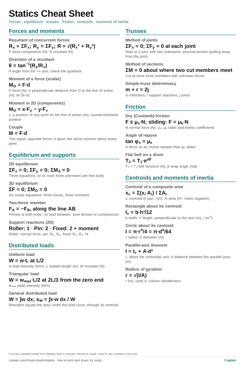
Every statics formula from a first engineering mechanics course on one page: force resultants, moments, the equilibrium equations, support reactions, trusses, friction, centroids and area moments of inertia. Each line lists its variables and SI units.
Forces and moments: formula, then every variable with its unit
Quantity
Formula
Variables and units
Resultant of concurrent forces
Rx = ΣFx; Ry = ΣFy; R = √(Rx² + Ry²)
F force components (N); R resultant (N)
Direction of a resultant
θ = tan−1(Ry/Rx)
θ angle from the +x axis; check the quadrant
Moment of a force (scalar)
MO = F·d
F force (N); d perpendicular distance from O to the line of action (m); M (N·m)
Moment in 2D (components)
MO = x·Fy − y·Fx
x, y position of any point on the line of action (m); counterclockwise positive
Couple
M = F·d
Two equal, opposite forces d apart; the same moment about every point
Equilibrium and supports
Equilibrium and supports: formula, then every variable with its unit
Quantity
Formula
Variables and units
2D equilibrium
ΣFx = 0; ΣFy = 0; ΣMA = 0
Three equations, so at most three unknowns per free body
3D equilibrium
ΣF = 0; ΣMO = 0
Six scalar equations: three forces, three moments
Two-force member
FA = −FB, along the line AB
Pinned at both ends, no load between: pure tension or compression
Support reactions (2D)
Roller: 1 · Pin: 2 · Fixed: 2 + moment
Roller: normal force; pin: Rx, Ry; fixed: Rx, Ry, M
Distributed loads
Distributed loads: formula, then every variable with its unit
Quantity
Formula
Variables and units
Uniform load
W = w·L at L/2
w load intensity (N/m); L loaded length (m); W resultant (N)
Triangular load
W = wmax·L/2 at 2L/3 from the zero end
wmax peak intensity (N/m)
General distributed load
W = ∫w dx; xW = ∫x·w dx / W
Resultant equals the area under the load curve, through its centroid
Trusses
Trusses: formula, then every variable with its unit
Quantity
Formula
Variables and units
Method of joints
ΣFx = 0; ΣFy = 0 at each joint
Start at a joint with two unknowns; assume tension (pulling away from the joint)
Method of sections
ΣM = 0 about where two cut members meet
Cut at most three members with unknown forces
Simple-truss determinacy
m + r = 2j
m members; r support reactions; j joints
Friction
Friction: formula, then every variable with its unit
Quantity
Formula
Variables and units
Dry (Coulomb) friction
F ≤ μs·N; sliding: F = μk·N
N normal force (N); μs, μk static and kinetic coefficients
Angle of repose
tan φs = μs
A block on an incline steeper than φs slides
Flat belt on a drum
T2 = T1·eμβ
T2 > T1 belt tensions (N); β wrap angle (rad)
Centroids and moments of inertia
Centroids and moments of inertia: formula, then every variable with its unit
Quantity
Formula
Variables and units
Centroid of a composite area
xc = Σ(xi·Ai) / ΣAi
xi centroid of part i (m); Ai area (m², holes negative)
Rectangle about its centroid
Ix = b·h³/12
b width; h height, perpendicular to the axis (m); I (m4)
Circle about its centroid
I = π·r4/4 = π·d4/64
r radius; d diameter (m)
Parallel-axis theorem
I = Ic + A·d²
Ic about the centroidal axis; d distance between the parallel axes (m)
Radius of gyration
r = √(I/A)
r (m); used in column slenderness
How to use this cheat sheet
Draw the free body diagram before you pick an equation. The sheet tells you what to write once every force is on the diagram; it cannot tell you which forces belong there.
Take moments about the point where the most unknown forces act. Each force through that point drops out of the moment equation, which often leaves one unknown.
Keep a sign convention on the page (counterclockwise positive, tension positive) and stick to it. A negative answer then means the force acts opposite to the direction you assumed, not that you made a mistake.
Example: Reactions on a beam with a point load and a uniform load
Given
Beam AB, 6 m long; pin at A (left end), roller at B (right end)
Downward point load of 12 kN, 2 m from A
Uniform downward load of 4 kN/m over the right-hand 3 m (from x = 3 m to x = 6 m)
Find
The support reactions A_x, A_y and B_y
Solution
Replace the uniform load with its resultant at the middle of its length.W = 4 kN/m × 3 m = 12 kN at x = 4.5 m
There are no horizontal loads.ΣF_x = 0 → A_x = 0
Take moments about A so A_x and A_y drop out (counterclockwise positive).ΣM_A = B_y(6) − 12(2) − 12(4.5) = 0 → B_y = 78/6 = 13 kN
The PDF is one US Letter page that also prints on A4 without cropping. The 2:3 PNG is the same sheet as an image, sized for a phone lock screen or a pin. Both are made from the formulas in the tables above, so they always match.
Very few: the equilibrium equations, the definition of a moment, and the friction inequality. Most of the work is drawing correct free body diagrams. Centroid and moment-of-inertia formulas for basic shapes are usually given in tables.
Why does my answer come out negative?
A negative force means it acts opposite to the direction you assumed on the free body diagram. Keep the sign and report the direction; do not go back and flip the diagram mid-solution.
When do I use the method of sections instead of joints?
When you need the force in one or two members in the middle of a large truss. One cut and one moment equation is faster than solving joint after joint.