GD&T Cheat Sheet

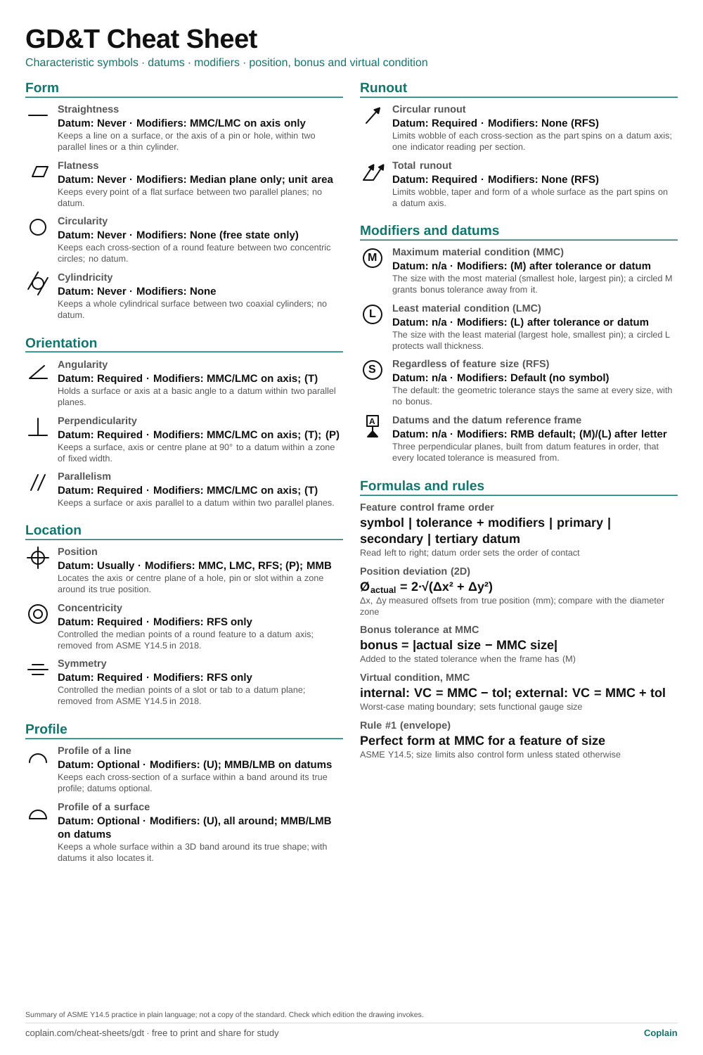
A one-page GD&T quick reference: every geometric characteristic symbol grouped by type, whether it needs a datum, which material condition modifiers it accepts, and the formulas used to check position, bonus tolerance and virtual condition. Each symbol links to its full page.

What’s on the sheet

Form

Form: symbol, datum and modifier rules, and what each one controls
SymbolCharacteristicDatum and modifiersWhat it controls
StraightnessDatum: Never · Modifiers: MMC/LMC on axis onlyKeeps a line on a surface, or the axis of a pin or hole, within two parallel lines or a thin cylinder.
FlatnessDatum: Never · Modifiers: Median plane only; unit areaKeeps every point of a flat surface between two parallel planes; no datum.
CircularityDatum: Never · Modifiers: None (free state only)Keeps each cross-section of a round feature between two concentric circles; no datum.
CylindricityDatum: Never · Modifiers: NoneKeeps a whole cylindrical surface between two coaxial cylinders; no datum.

Orientation

Orientation: symbol, datum and modifier rules, and what each one controls
SymbolCharacteristicDatum and modifiersWhat it controls
AngularityDatum: Required · Modifiers: MMC/LMC on axis; ⓉHolds a surface or axis at a basic angle to a datum within two parallel planes.
PerpendicularityDatum: Required · Modifiers: MMC/LMC on axis; Ⓣ; ⓅKeeps a surface, axis or centre plane at 90° to a datum within a zone of fixed width.
ParallelismDatum: Required · Modifiers: MMC/LMC on axis; ⓉKeeps a surface or axis parallel to a datum within two parallel planes.

Location

Location: symbol, datum and modifier rules, and what each one controls
SymbolCharacteristicDatum and modifiersWhat it controls
PositionDatum: Usually · Modifiers: MMC, LMC, RFS; Ⓟ; MMBLocates the axis or centre plane of a hole, pin or slot within a zone around its true position.
ConcentricityDatum: Required · Modifiers: RFS onlyControlled the median points of a round feature to a datum axis; removed from ASME Y14.5 in 2018.
SymmetryDatum: Required · Modifiers: RFS onlyControlled the median points of a slot or tab to a datum plane; removed from ASME Y14.5 in 2018.

Profile

Profile: symbol, datum and modifier rules, and what each one controls
SymbolCharacteristicDatum and modifiersWhat it controls
Profile of a lineDatum: Optional · Modifiers: Ⓤ; MMB/LMB on datumsKeeps each cross-section of a surface within a band around its true profile; datums optional.
Profile of a surfaceDatum: Optional · Modifiers: Ⓤ, all around; MMB/LMB on datumsKeeps a whole surface within a 3D band around its true shape; with datums it also locates it.

Runout

Runout: symbol, datum and modifier rules, and what each one controls
SymbolCharacteristicDatum and modifiersWhat it controls
Circular runoutDatum: Required · Modifiers: None (RFS)Limits wobble of each cross-section as the part spins on a datum axis; one indicator reading per section.
Total runoutDatum: Required · Modifiers: None (RFS)Limits wobble, taper and form of a whole surface as the part spins on a datum axis.

Modifiers and datums

Modifiers and datums: symbol, datum and modifier rules, and what each one controls
SymbolCharacteristicDatum and modifiersWhat it controls
Maximum material condition (MMC)Datum: n/a · Modifiers: Ⓜ after tolerance or datumThe size with the most material (smallest hole, largest pin); a circled M grants bonus tolerance away from it.
Least material condition (LMC)Datum: n/a · Modifiers: Ⓛ after tolerance or datumThe size with the least material (largest hole, smallest pin); a circled L protects wall thickness.
Regardless of feature size (RFS)Datum: n/a · Modifiers: Default (no symbol)The default: the geometric tolerance stays the same at every size, with no bonus.
Datums and the datum reference frameDatum: n/a · Modifiers: RMB default; Ⓜ/Ⓛ after letterThree perpendicular planes, built from datum features in order, that every located tolerance is measured from.

Formulas and rules

Formulas and rules: formula, then every variable with its unit
QuantityFormulaVariables and units
Feature control frame ordersymbol | tolerance + modifiers | primary | secondary | tertiary datumRead left to right; datum order sets the order of contact
Position deviation (2D)Øactual = 2·√(Δx² + Δy²)Δx, Δy measured offsets from true position (mm); compare with the diameter zone
Bonus tolerance at MMCbonus = |actual size − MMC size|Added to the stated tolerance when the frame has Ⓜ
Virtual condition, MMCinternal: VC = MMC − tol; external: VC = MMC + tolWorst-case mating boundary; sets functional gauge size
Rule #1 (envelope)Perfect form at MMC for a feature of sizeASME Y14.5; size limits also control form unless stated otherwise

How to use this cheat sheet

Find the symbol in the left column, then read across: whether it needs a datum and which modifiers it accepts. If a drawing shows a modifier this sheet says the symbol cannot take, ask the designer before you inspect.

For a position callout with Ⓜ, compute the bonus from the measured size first, then compare the measured position diameter with the stated tolerance plus bonus.

Concentricity and symmetry were removed in ASME Y14.5-2018. They are listed because older drawings still use them; check which edition the drawing invokes.

Example: Position with bonus tolerance

Given

  • Hole size limit Ø10.0–10.4 mm, so the MMC size is Ø10.0
  • Feature control frame: position, Ø0.2 Ⓜ, datums A | B | C
  • Measured: hole Ø10.25 mm; centre offset from true position Δx = 0.12 mm, Δy = 0.09 mm

Find

  • The measured position deviation
  • The allowed position tolerance at this size
  • Whether the hole is acceptable for position

Solution

  1. Position deviation as a diameter zone.Ø_actual = 2·√(0.12² + 0.09²) = 2 × 0.15 = Ø0.30 mm
  2. The hole departs from MMC by its size difference, which becomes bonus tolerance.bonus = 10.25 − 10.00 = 0.25 mm
  3. Allowed tolerance at the measured size.Ø0.20 + 0.25 = Ø0.45 mm
  4. Compare.Ø0.30 ≤ Ø0.45 → accept

Answer: The hole is Ø0.30 from true position against an allowed Ø0.45 at its size, so it passes position (size must also be within Ø10.0–10.4, which it is).

Printable cheat sheet

The PDF is one US Letter page that also prints on A4 without cropping. The 2:3 PNG is the same sheet as an image, sized for a phone lock screen or a pin. Both are made from the formulas in the tables above, so they always match.

GD&T Cheat Sheet: Characteristic symbols · datums · modifiers · position, bonus and virtual condition
GD&T Cheat Sheet (PNG, 2:3)

Matching lessons and calculators

Learn where each formula comes from, then check your own numbers.

All engineering cheat sheets

Frequently asked questions

How many GD&T symbols are there?

ASME Y14.5-2018 has 12 geometric characteristic symbols; the 2009 edition had 14, including concentricity and symmetry, which this sheet keeps for older drawings. Modifiers such as Ⓜ, Ⓛ and Ⓟ are separate.

Which symbols never use a datum?

The form controls: straightness, flatness, circularity and cylindricity. They control a feature’s shape on its own, so a datum would have nothing to relate to.

Is this sheet a substitute for the standard?

No. It summarizes common rules in plain language. The governing standard is whichever edition of ASME Y14.5 or ISO 1101 the drawing invokes.
See also

More cheat sheets

Sources

  1. ASME Y14.5-2018 Dimensioning and Tolerancing, ASME
  2. ASME Y14.5-2009 Dimensioning and Tolerancing (for drawings made to the earlier edition), ASME
  3. ISO 1101 Geometrical product specifications (GPS) — Geometrical tolerancing, ISO

Last updated

COPLAIN AI PLATFORM

Generate yours automatically from your existing docs

Heading into manufacturing? Coplain turns engineering procedures into clear, audit-ready work instructions and job aids for the shop floor.

Generate yours automatically with Coplain →